| |
| We hope you enjoy "Project Rock Ripper". We started this project as rock crawling newbies and still have a lot to learn. Throughout the project pages, you will see what we did with our truck and we will also try to list some alternatives to get the job done. Our hope is that by providing some alternate methods to achieve the same end goal, more people will tackle a project like this and get into crawling! |
| |
|
INSTALLING THE MOTORS
Actually we installed the motors early on in our project to make sure there would not be any interference issues with the axle links or shocks.
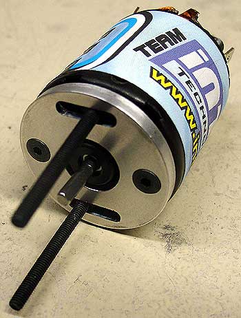
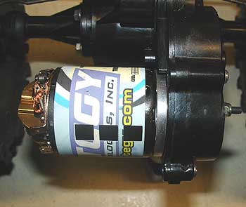
We chose Integy Lathe motors (55 turn) to drive our crawler. After reading up on the subject, they seemed to be the most popular choice and the price was right at about $20 per motor. A rock crawler needs a lot of torque, not speed, so we chose Robinson Racing 9 tooth pinion gears for our motors. In order to make these work, we needed to add adjustable motor mounts to allow the motors ample adjustment in relationship to the internal differential gear. ADJUSTABLE MOTOR MOUNTS
The Crawler Store offers some great adjustable motor mounts made by Thunder Tech. They sell for $29.99 and some with everything you need (pinion gears sold separately) to fully adjust your motors for a 9 tooth pinion setup.
The mount kit consists of slotted motor mounting plates and all the hardware required to make it happen. We did add some small washers to the lock nuts on the motor mounts however as we felt it would take some stress off the axle case. Note: When mounting the pinion gears, you can not slide them fully onto the motor shaft. If you do, the pinion gear set screw will chew on the axle drive gear (this is bad). Take your time on this step to get them positioned correctly. Our setup had the pinion gear mounted several millimeters past the end of the motor shaft. There is still sufficient surface area...just make sure you mount the pinion set screw against the flat part of the motor shaft for optimal holding strength and apply some blue thread locker to the pinion set screw as well. FLIP THE MOTOR END CAP...REVERSE THE REAR MOTOR
The front and rear Clod axles are the same. The rear axle is turned 180 degrees (backwards) when compared to the front. Because of this, you will need to reverse the direction of the rear motor so it turns the same direction as the front motor. If we lost you, just trust us. You have to do this step!
This is a simple thing to do. First, disengage the brush springs from the end cap and pull the brushes out slightly, just enough to move them away from the comm. Remove the two phillips head screws that hold the end cap on, spin the end cap 180 degrees and reinstall the screws. Slide the brushes back into the end cap and reinstall the brush springs. It is also a good idea to take a permanent maker and make a "R" on the motor label so you remember which one is reversed. INSTALLING THE ELECTRONIC SPEED CONTROL
There are several options for an ESC in a Crawler.
You should take into consideration the motors you will be using, the
number of batteries you want to use and your budget of course. Many
people use the Novak Super Rooster or the Traxxas EVX ESC as they
are readily available (Super Rooster is discontinued by you can still
find them). We searched around and ultimately decided upon a Novak
XR Super Duty. It is a killer ESC, can handle lots of volts and truthfully
is a little overkill for this project. The only bad thing about it
is its size. It is a big unit and narrowly fit into our chassis (we
actually built our chassis wide enough to handle it...just barely).
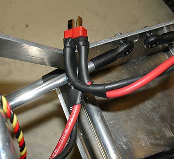
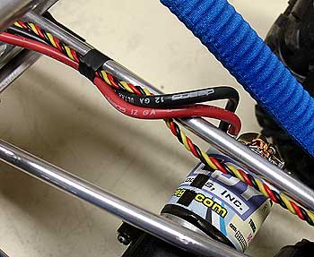
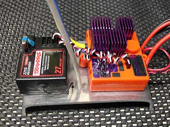
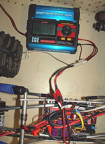
We modified the ESC to run on one battery (steps are included in the Novak instructions) as we plan on running a single LiPo, 3-cell battery in it initially. Next it was time to wire up the motors. We chose to wire our rock blasting beast via a parallel connection to the motors. A simple "Y" connection at the ESC splits the power to the front and rear motors. We soldered in a Deans Ultra Plug at the "Y" so we could unhook one plug and detach the ESC from both motors. It can be argued that you should not use plugs between the ESC and the motors for resistance issues etc but we wanted to try it from a convenience standpoint. INSTALLING THE RECEIVER We "cheaped out" on this step and just used an old Traxxas T-Maxx AM receiver we had stashed in our parts bin. It should work perfectly as it has a third channel which we will use for the rear steering servo. This also works well as we are going to modify a Traxxas TQ3 transmitter (stock T-Maxx) to control the rear steering of our truck (see below).
THE WIRE and CONNECTORS
The electrical pipeline we chose was Deans 12 gauge Ultra Wire. Luck was with us one day as we were digging through the discount bin at our LHS (we have no shame and love good deals). Alas at the bottom of the bin were two, 25' packs of Deans Ultra Wire. Normally each pack sells for $35 but it was 50% off! We paid $35 for 50' of Ultra Wire! Granted we only needed a couple of feet but the deal was too good to pass up. We have enough high quality wire to last us for years!
The wire was routed to avoid any pinch points near the axle links and chassis. This is the part we dread the most. Running the wire. Why you ask? Well, it is hard to get a bunch of spaghetti to look good! Time, patience and planning all come into play and help the final look. Slices of heat shrink tubing were used to secure the wire to the axle links on its way back to the ESC. It is a slightly cleaner look than a zip tie and works very well. Deans Ultra Plugs were used throughout our project. They fit tight, work great and are easy to solder. We also used Deans Racing Solder on all our connections. It is $4 a tube, it flows like silk and it will last you a long time. We have been using the same tube for close to a year and still have half of it left! It is a bargain. REMOVABLE RADIO TRAY
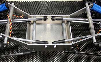
We designed the truck to have a removable radio
tray. The receiver and ESC are mounted to a piece of bent 6061
aluminum that can be removed by loosening one screw. The batteries
reside under this tray, keeping them out of harms way. A couple
of holes were drilled to mount the antenna tube (time will tell
how well this is going to work....we have some doubts). The power
switch is mounted to the outside of the chassis via a small piece
of Velcro. To remove the tray, simply remove one screw, unplug
the Y connector for the motors, unattach the power switch and
unplug the two servos. It turned out to be a tighter fit than we
had planned but nonetheless, it works pretty slick!
MODIFYING THE TRANSMITTER FOR 4-WHEEL STEERING
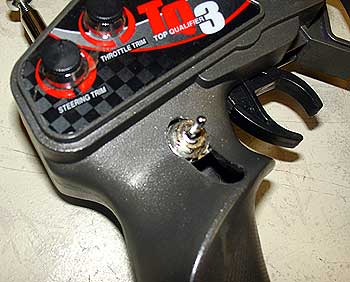
The Traxxas TQ3 transmitter (stock T-Maxx & E-Maxx) is perfect for a crawling machine and is one of the more popular models in the crawling crowd. The reason being it has a third channel switch, mounted in a good location.
The switch itself would need to be replaced as we wanted a left, neutral and right steering position. The stock, rocker type switch is difficult to hold in the center (neutral) position so a three position switch would be a much better option. We tore the TQ3 down to see the overall size of the current switch and to see what the wiring looked like. Three wires ran to the stock switch so we would need a switch that could handle the same. 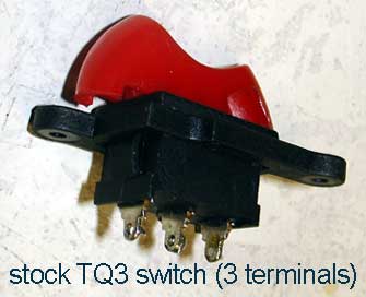
Off we went to buy a new switch! Where else would we go but Radio Shack! We hit the Shack and pilfered through their switch bins for a few minutes and there it was! A 3 position switch that was the right size to fit inside the TQ3 and it had three position terminals (it had 6 terminals in all, two rows of three...we just utilized one row of the terminals). We un-soldered the three wires from the stock switch and re-soldered them onto the new switch in the same order. The switch slid through the existing opening, a quick washer and nut and that's it! This may sound like a difficult thing to do but if you have the ability to wire up an electric vehicle and can use a soldering iron, you are good to go. Alternatives to the Transmitter Modifications: - The Crawler Store (they sell a switch package for $9) - The Crawler Store (they also sell TQ3's already modified complete with a receiver and crystals for only $65...this is a good deal!) BATTERY OPTIONS There are two common options available for battery
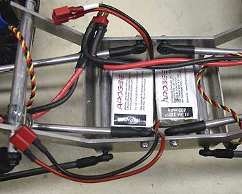
power. NiMH or LiPo. We chose LiPo power as we wanted the battery
mounted on the chassis for a cleaner look, rather than having it mounted
to the axles. LiPo's are so lightweight, the center of gravity would
be affected very little by mounting it in the main chassis. In fact
we designed the battery mounting area large enough to hold two 830
LiPo batteries so when one dies, we can just plug in the other battery
and keep going. The leads are long enough that we can easily charge
the batteries in the vehicle without removing them.
Yet again, we cheaped out and used batteries we had in our stash, two Apogee 3-cell Lipo 830mah bad boys. We were fairly certain the 830mah would leave us with short run times (two motors and two servos sucking lots of power) however we thought it was worth a try! At the very least, it will give us an idea on how many mah's we need to upgrade to in the future in order to get the run times we want. Example: if the 830mah lasts 15 minutes, a 2000mah should last about 35 minutes. When using LiPo in a truck like a rock crawler, you really need to pay attention to the following things: 1. As soon as the truck starts losing power, stop using it. You do not want to go less than 3 volts per cell on the discharge side. If you stop immediately when the truck starts to slow down, you should be fine. 2. Avoid stalls. This is hard on any battery. When the truck "stalls" meaning the tires are wedged or otherwise rendered stuck and you are pouring the juice to it, it can short a battery. If your wheels get wedged, lay off the power and get your truck unstuck! 3. Keep the battery well protected . This is especially important with Lithium batteries. They are physically more fragile than NiCD or NiMH cells and need to be well protected from sticks or other foreign objects you might run into. Note: We also have some IB 3800mah NiMH cells that we will be using in our XXX-T and then will use in our Crawler. They should work great The 6 cells will be split into two 3-packs and mount one pack on each axle to keep the weight low and even. Stay tuned for this modification at a later date. Click here to check out STAGE 8 of Project Rock Ripper.....Body and Finish Work. |
© Copyright
2001-2006 Beat Your Truck. Site best viewed at 800x600 or higher with Internet Explorer 5.5 or higher.
Advertise with Beat Your Truck * Donate to Beat Your Truck
Advertise with Beat Your Truck * Donate to Beat Your Truck